Recent Trends in Fluid Catalytic Cracking Patents, Part V: Reactor Section
Sep 3rd, 2014 by William Reid | News | Recent News & Articles |
Fluid Catalytic Cracking Patents (V): Reactor Section – 2012-2013[1]
This is the fifth article in a review of recent patents in the area of Fluid Catalytic Cracking (FCC). The first four articles reviewed patents on catalyst additives, zeolites, cyclones, and cracking catalysts. The current article will cover seven patents relating to the FCC reactor system, which for the purposes of this article includes the riser(s), separation devices, stripper and the reactor vessel. The reactor section patents can generally be placed into two groups. The first group contains three patents: U.S. Patent Nos. 8,128,807, 8,349,170, and 8,383,051, and relate to the particular configuration of the riser and the primary/secondary separation devices. The second group contains two patents: U.S. Patent Nos. 8,354,018 and 8,394,259, which relate to dual riser systems. Another patent, U.S. Patent No. 8,124,020, relates to an apparatus containing a sulfiding agent line. While its claims are not limited to a dual riser system, they are described in the specification as being useful in such a system. A final patent, U.S. Patent No. 8,124,020, does not fall into the either of the above groups, but relates to the use of torch oil in a reactor stripper section. Review of the patents indicates a significant effort in reactor design research is ongoing, at least for the purposes of filing patent applications, since they are largely directed to fundamental aspects of the reactor/riser/separator configuration.
The patents related to the reactor section are summarized below. Table 1 lists relevant information in the patents. Table 2 contains a representative independent claim from each.
Reactor Section
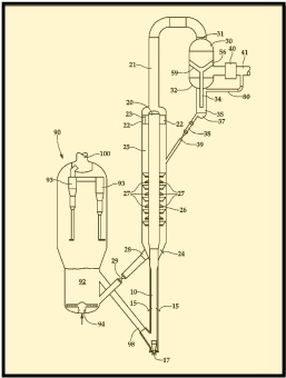
In the first group of patents, U.S. Patent No. 8,128,807 describes a system where the riser 10 terminates in a primary separator 20 (Figure 1). Cracked hydrocarbon and catalyst are partially separated in the primary separator 20. The resultant gas stream is then routed from the riser 10 through a conduit 21 to multi-cyclone separator 30 comprising multiple cyclones 53 that extend through a tube sheet, where further catalyst removal is conducted. Catalyst particles separated in the multi-cyclone separator 30 are routed to the stripping section 26.
U.S. Patent No. 8,349,170 describes inter alia, a riser configuration consisting of a lower reactor riser section and an upper reactor riser section. The upper riser contains an upper conical shaped section which is connected at the large end of the cone to a cylindrical sleeve that fits concentrically around and overlaps a portion of the lower riser. The upper riser/conical section is in fluid contact (not mechanical contact) with the lower riser. Such a design is described as improving both mechanical reliability and process performance.
U.S. Patent No. 8,383,051 describes a compact riser separation system having an external riser 41 that enters a reactor vessel shell 51 from the outside via a crossover conduit 46.
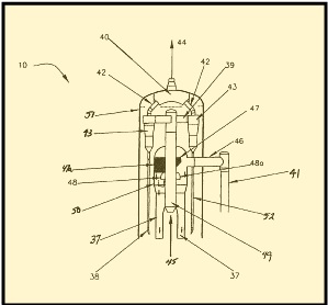
In the second group of patents, U.S. Patent No. 8,354,018 describes a process for catalytically converting two feed streams in two separate reactors. Catalyst and a first hydrocarbon feed (for the first reactor 10), such as a virgin gas oil, is preheated in a wash column 30 by contacting it with a second cracked product stream from the second reactor 200, before feeding to the first reactor 10, to produce a first cracked product stream. Catalyst and a portion of the cracked products from the first reactor 10 are fed to second reactor 200 to form a second cracked product stream. Effluent from the first and second reactors is processed separately.
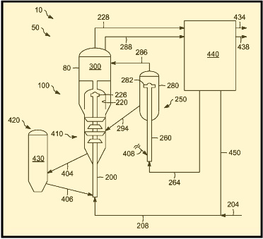
U.S. Patent No. 8,394,259 describes a process for producing gasoline and propylene. A first stream having a boiling point range of about 180°C to 800°C is catalytically cracked in a first reaction zone 100 (first riser 200/first reaction vessel 220). A second stream containing C4-C6 olefins is catalytically cracked in a second reaction zone 250 (second riser 260/second reaction vessel 280). A first mixture of catalyst and products from the first reaction zone 100 and a second mixture of catalyst and products from the second reaction zone 250 are received in a disengagement zone 440 contained by a shell.
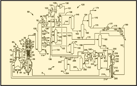
U.S. Patent No. 8,124,020 describes an FCC apparatus having a riser 12, catalyst pipe 14, feed line 8, feed distributors 22, reactor vessel 20 in communication with the riser 12 for receiving products and catalyst from the riser 12, and a sulfiding agent line 186, distinct from the feed line, in communication with the riser 12. Addition of the sulfiding agent prevents excessive coke formation resulting from Metal Catalyzed Coking. The specification describes a dual riser system where the sulfiding agent line 186 is utilized in a second reactor 170. The second reactor feed can include C10-hydrocarbons, and preferably C4 to C10 olefins.
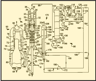
A final patent, U.S. Patent No. 8,506,795 describes a process for providing torch oil to a stripping section 250 of a first reaction zone 200. Torch oil is sometimes added to an FCC regenerator when the feed is so light as to produce insufficient amounts of coke to maintain the regenerator temperature. Addition of the torch oil to the regenerator sometimes results in hot spots that can sinter typical FCC catalysts, degrading their activity and yield selectivities. Adding the torch oil to the stripping section in this manner facilitates raising regenerator temperatures to desired levels. The specification describes a dual riser system where a light hydrocarbon feed is fed to a first riser 240, and heavy hydrocarbon fed to a second riser 340. Torch oil is added to stripping section 250 of the riser processing the light feed through line 144.
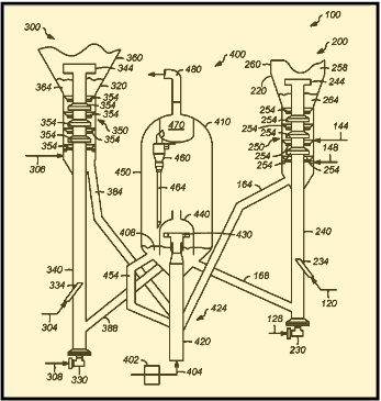
Table 1
FCC Patents — Reactor
| Patent Number | Inventor | Assignee | Title | Issue Date |
| U.S. 8,124,020 | Couch et al. | UOP LLC | Apparatus For Preventing Metal Catalyzed Coking | February 28, 2012 |
| U.S. 8,128,807 | Seibert et al. | UOP LLC | FCC Separator Without A Reactor | March 6, 2012 |
| U.S. 8,349,170 | Tammera et al. | ExxonMobil Research and Engineering Company | FCC Reactor And Riser Design For Short Contact-Time Catalytic Cracking Of Hydrocarbons. | September 3, 2013 |
| U.S. 8,354,018 | Leonard et al. | UOP LLC | Process For Recovering Products From Two Reactors | January 15, 2013 |
| U.S. 8,383,051 | Gbordzoe et al. | Stone & Webster Process Technology, Inc. | Separating And Stripping Apparatus For External FCC Risers | February 26, 2013 |
| U.S. 8,394,259 | Palmas et al. | UOP LLC | Unit, System And Process For Catalytic Cracking | March 12, 2013 |
| U.S. 8,506,795 | Palmas et al. | UOP LLC | Process For Fluid Catalytic Cracking | August 13, 2013 |
Table 2.
FCC Reactor Claims
| Patent Number | Independent Claim |
| U.S. 8,124,020 | Claim 1. A fluid catalytic cracking apparatus, comprising: a riser for contacting a hydrocarbon feed with catalyst to produce products; a catalyst pipe in communication with said riser for delivering catalyst to said riser; a feed line for carrying hydrocarbon feed; a feed distributor in communication said feed line and with said riser for delivering said hydrocarbon feed to said riser; a reactor vessel in communication with said riser for receiving products and catalyst from said riser; and a sulfiding agent line, distinct from said feed line, in communication with said riser. |
| U.S. 8,128,807 | Claim 1. A process for fluid catalytic cracking, comprising: fluidizing a hydrocarbon stream in a riser; cracking said hydrocarbon stream with catalyst in said riser to produce a cracked stream and spent catalyst; separating said cracked stream and said spent catalyst in a primary separator to obtain a cracked stream with a first concentration of spent catalyst; and transporting said cracked stream with said first concentration of spent catalyst through a conduit to a multi-cyclone separator comprising multiple cyclones extending through a tube sheet to obtain a cracked stream with a second concentration of spent catalyst. |
| U.S. 8,349,170 | Claim 1. A fluid catalytic cracking process, comprising: a) injecting a heavy hydrocarbon feed through one or more feed nozzles connected to an external fluid cracking reactor riser section wherein the external fluid cracking reactor riser section is in fluid connection with a lower internal reactor riser located inside of a fluid catalytic cracking reactor vessel; b) contacting the heavy hydrocarbon feed with a hot fluidized catalyst in the external fluid cracking reactor riser; c) passing at least a portion of the heavy hydrocarbon feed and the hot fluidized catalyst through the lower internal reactor riser; d) passing at least a portion of the heavy hydrocarbon feed and the hot fluidized catalyst from the lower internal reactor riser to an upper internal reactor riser; and e) retrieving a fluid catalytically cracked product stream and a spent catalyst stream from the fluid catalytic cracking reactor vessel; wherein at least a portion of the heavy hydrocarbon feed is catalytically cracked into lower molecular weight hydrocarbon compounds which are retrieved as the fluid catalytically cracked product stream; and wherein said fluid catalytic cracking reactor vessel, comprises: said lower internal reactor riser, wherein the lower end of the lower internal reactor riser is attached to the shell of the fluid catalytic cracking reactor vessel; and said upper internal reactor riser wherein the lower end of the upper internal reactor riser terminates in a conical section which is connected to a cylindrical sleeve section; wherein the upper section of the upper internal reactor riser is not in fluid connection with the dilute phase section of the reactor vessel, and at least two riser outlet ports are mechanically connected to the upper section of the upper internal reactor riser: and wherein the upper end of the lower internal reactor riser is in fluid connection with the upper internal reactor riser and the dilute phase section of the reactor vessel; the upper end of the lower internal reactor riser is not mechanically connected to the upper internal reactor riser; the largest diameter of the conical section of the upper internal reactor riser is larger than the diameter of the upper end of the lower internal reactor riser; the cylindrical sleeve of the upper internal reactor riser has a diameter larger than the diameter of the upper end of the lower internal reactor riser; at least a portion of the cylindrical sleeve of the upper internal reactor riser overlaps with at least a portion of the upper end of the lower internal reactor riser; and there is no mechanical means located in the region of the overlapping portion of the cylindrical sleeve of the upper internal reactor riser and the upper end of the lower internal reactor riser for restricting the eccentricity between the cylindrical sleeve and the upper end of the lower internal reactor riser. |
| U.S. 8,354,018 | Claim 1. A catalytic cracking process comprising: feeding a first hydrocarbon feed to a wash column; feeding said hydrocarbon feed from said wash column to a first reactor; delivering catalyst to said first reactor; contacting said first hydrocarbon feed with said catalyst to provide first cracked products; feeding a portion of said first cracked products as a second hydrocarbon feed to a second reactor; delivering catalyst to said second reactor; contacting said second hydrocarbon feed with said catalyst to provide second cracked products; and feeding said second cracked products to said wash column. |
| U.S. 8,383,051 | Claim 1. An apparatus for separating and stripping a gaseous mixture and a stream of particles which comprises: a reactor vessel shell having a means for a riser cross-over conduit from a riser reactor pipe located external to said reactor vessel shell for transferring a mixture of cracked gases and spent catalytic solid particles, the reactor vessel shell comprising an upper dilute portion and a lower stripping bed portion, said riser cross-over conduit is in fluid communication with the riser reactor pipe and at least one separating chamber for receiving said mixture of cracked gases and spent catalytic solid particles from said cross-over conduit for separating spent catalytic particulates from the cracked gases located within said reactor vessel shell and comprising a dipleg for discharging separated catalytic particulates into said lower stripping bed portion; a stripping chamber comprising at least one inlet opening communicating with said at least one separating chamber for receiving separated cracked gases from said separating chamber; a stripper vapor inlet opening for receiving stripping gas from said stripping bed portion and a stripper conduit for evacuating vapors from said stripping chamber; and, at least one cyclone separator for receiving vapors from said stripping chamber and comprising at least one cyclone separator dipleg having an outlet for returning separated solids to the stripping bed and a vapor evacuation conduit for discharging vapors to a gas outlet collector which communicates with a vapor outlet conduit for removing separated vapors from said reactor vessel shell, wherein said stripping chamber is positioned centrally within said reactor shell and said at least one separating chamber is positioned axially about said stripping chamber and wherein said stripping chamber ascends centrally through said at least one separating chamber from a position below to a position above said at least one separating chamber. |
| U.S. 8,394,259 | Claim 1. A process for producing gasoline and propylene, comprising: A) passing a first stream through a first reaction zone comprising a first riser and a first reaction vessel having a first volume wherein the first stream has a boiling point range of about 180° to about 800° C.; B) passing a second stream through a second reaction zone comprising a second riser and a second reaction vessel having a second volume wherein the second stream comprises an effective amount of C4-C6 olefins for producing propylene; wherein the first volume is greater than the second volume; and C) receiving a first mixture comprising at least one catalyst and one or more products from the first reaction zone, and a second mixture comprising at least one catalyst and one or more products from the second reaction zone in a disengagement zone contained by a shell. |
| U.S. 8,506,795 | Claim 1. A process for fluid catalytic cracking, comprising: A) providing a torch oil to a stripping section of a first reaction zone, which in turn communicates at least a partially spent catalyst to a regeneration zone for providing additional heat duty to the regeneration zone. |
[1] My thanks to Mr. Ken Peccatiello of Peccatiello Engineering (www.PeccatielloEngineering.com) for reviewing the text.
– Bill Reid
Check out Bill’s bio page
This article is for informational purposes, is not intended to constitute legal advice, and may be considered advertising under applicable state laws. The opinions expressed in this article are those of the author only and are not necessarily shared by Dilworth IP, its other attorneys, agents, or staff, or its clients.