Recent Trends in Fluid Catalytic Cracking Patents, Part VI: Regenerator
Mar 18th, 2015 by William Reid | News | Recent News & Articles |
Fluid Catalytic Cracking Patents (VI): Regenerator 2012-2013[1]
This is the sixth and final article in a review of patents in the area of Fluid Catalytic Cracking (FCC) for 2012-2013. The next article in this series will focus on FCC patents from 2014. The first five articles reviewed patents on catalyst additives, zeolites, cyclones, cracking catalysts and reactors. The current article will cover eight patents relating to FCC regenerators. Five of the eight patents relate to better mixing of the coked catalyst in the regenerator aimed at improving catalyst distribution, and permitting more even burning. These include systems to mix the coked catalyst with regenerated catalyst, systems to mix the coked catalyst with a carrier fluid, and systems to provide better mixing with combustion air. Of the three remaining patents, one relates to the use of a catalyst cooler, another relates to a fuel nozzle configuration for providing reactor heat demands for light feedstocks. The last relates to a two-step regenerator for operating at an increased level of coke on the catalyst. The accompanying reduced catalyst activity is useful for operating in a max-LCO mode.
Review of the patents indicates that substantial effort in regenerator design and implementation continues, particularly in the area of catalyst and combustion air mixing and/or distribution within the regenerator. The goal is to obtain as perfectly uniform distribution of the coked catalyst and combustion air within the regenerator as possible. A uniform distribution of coked catalyst and combustion air provides for efficient combustion of the coked catalyst. This results in more even or uniform burning, reduced after burn (lower temperatures where there is no catalyst to act as a heat-sink or absorber of the heat generated), improved environmental emissions (lower NOX), less destruction of the catalyst (improved activity retention) and less damage to the internal hardware/equipment.
The patents related to the regenerator are summarized below. Attached Table 1 lists relevant information on the patents. Table 2 contains a representative independent claim from each.
Regenerator
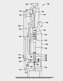
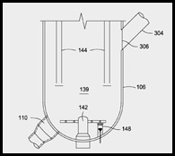
U.S. Patent No. 8,383,052 generally relates to a fuel nozzle configuration for providing heat demand while processing light feedstock. The claims are directed to a regenerator (106) having a heater (148), where the heater (148) is equipped with a fuel nozzle (204) for ejecting a mixture of fuel and oxygen-lean gas. The body (202) of the heater (148) has a number of windows (208) at one end of the body (202), where the vaporized mixture of fuel and oxygen-lean gas (210) exit the heater (148) into the dense phase catalyst bed (139).
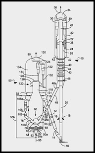
U.S. Patent No. 8,535,610 generally relates to a system for improved mixing of spent catalyst with regenerated catalyst. The regenerator design prevents after burn by providing a uniform mixture of spent and regenerated catalyst, with a more uniform temperature profile. The claims are directed to a first chamber (54) containing a gas distributer (80) and a cup (62), with a reactor catalyst conduit (48) extending to the cup (62). Recycled catalyst and spent catalyst are mixed in the cup (62) to raise the temperature of the spent catalyst before regeneration.
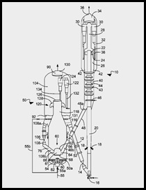
U.S. Patent No. 8,563,455 generally relates to a system for the mixing of spent catalyst with regenerated catalyst. The design prevents after burn by providing a uniform mixture of spent and regenerated catalyst having a uniform temperature profile. The claims are directed to a process where coke-containing spent catalyst is delivered to the regenerator where it is contacted with oxygen. The coke is combusted to produce regenerated catalyst and flue gas. The regenerated catalyst is separated from the flue gas and recycled to a cup (62) in the regenerator (50) where it is mixed with spent catalyst. The mixture then exits downwardly.
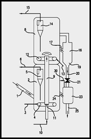
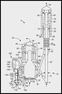
U.S. Patent No. 8,551,326 generally relates to a process for catalytically cracking a hydrocarbon feed using a regenerator having a first regeneration stage (2) that operates in partial combustion, and a second regeneration stage (8) operating in total combustion. Both stages contain fluidized beds. The catalyst residual coke rate from the first stage is between 0.3% and 0.7%, and less than 0.15% from the second stage (8). Catalyst flows from the first stage (2) to the second stage (8) via a transfer line (9) fed by a gas flow rate (10). The catalyst flow rate in the transfer line (9) is controlled by a plug valve (11) in the bottom of the transfer line (9). Operating at increased coke levels on the regenerated catalyst reduces the activity of the catalyst, which can be used for maximum-LCO operation.
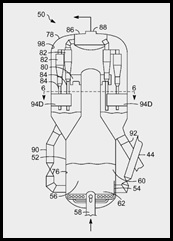
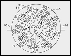
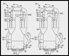
U.S. Patent No. 8,575,053 generally relates to a process for increasing mixing in a regenerator (50) using a dampening device. Such a device can be used to cause a mixing of streams of combustion air and streams of spent catalyst. Catalyst is introduced into the regenerator (50) through an inlet (54). Distribution gas is introduced below the inlet (54), and the catalyst and gas is lifted. Streamlines of gas in the dilute catalyst phase of the regenerator are dampened by redirecting the streamline, and catalyst is separated from the gas. The dampening device (94) can be a baffle (94D), a swirl arm (94A), a secondary T-disengager (94B) or an inverted can disengage (94C).Better mixing in the regenerator provides more uniform burning and reduced after burn.
U.S. Patent No. 8,609,566 generally relates to a process for regenerating catalyst in a regenerator (30) having a catalyst cooler (100). Coke on a catalyst is combusted in a combustor chamber in the regenerator (30) and flue gas is separated from the catalyst in a disengaging vessel. Hot catalyst is transferred from the regenerator (30) to the catalyst cooler (100) through a hot catalyst inlet (106) where it is cooled. Catalyst in the cooler (100) is fluidized with air and withdrawn from the cooler (100). Air from the cooler (100) is vented to the combustor chamber.
U.S. Patent No. 8,618,011 generally relates to the mixing of coked catalyst with a carrier fluid where the mixture is introduced to the upper surface (149) of the regenerator dense phase zone (145). The claims are directed to a process for regenerating catalyst where a hydrocarbon is cracked to produce a cracked hydrocarbon and coked catalyst particles. The coked catalyst particles are separated from the cracked hydrocarbons and then mixed with a carrier fluid and introduced to the dilute phase catalyst zone (155) through a distributor (150) onto the upper surface (149) of the regenerator dense phase (145). A gas is introduced into the lower zone of the dense phase (145), and the carbon is burned off the catalyst to provide a flue gas, heat and a regenerated catalyst.
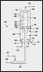
U.S. Patent No. 8,618,012 describes a process for regenerating a spent catalyst where the spent catalyst is mixed with a carrier fluid containing an oxygen-containing gas. The mixture is then introduced to or above the upper surface (149) the regenerator (140) dense phase catalyst zone (145). A gas is introduced into the lower zone of the dense phase (145), and the carbon is burned off the catalyst to provide a flue gas, heat and a regenerated catalyst.
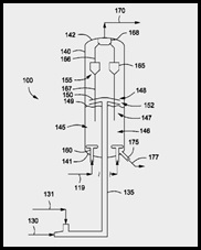
Table 1
FCC Patents — Regenerator
| Patent Number | Inventor | Assignee | Title | Issue Date |
| U.S. 8,383,052 | Niccum | Kellogg Brown & Root | System For A Heat Balanced FCC For Light Hydrocarbon Feeds | February 26, 2013 |
| U.S. 8,535,610 | Palmas et al. | UOP LLC | Apparatus For Regenerating Catalyst | September 17, 2013 |
| U.S. 8,563,455 | Palmas et al. | UOP LLC | Process For Regenerating Catalyst | October 22, 2013 |
| U.S. 8,551,326 | Roux et al. | IFP Energies Nouvelles | Process For Catalytic Cracking With Fine Control Of The Residual Coke Content On The Catalyst After Regeneration. | October 8, 2013 |
| U.S. 8,575,053 | Mehlberg et al. | UOP LLC | Process For Regenerating Mixing | November 5, 2013 |
| U.S. 8,609,566 | Palmas et al. | UOP LLC | Process For Venting A Catalyst Cooler | December 17, 2013 |
| U.S. 8,618,011 | Niccum et al. | Kellogg Brown & Root LLC | Systems And Methods For Regenerating A Spent Catalyst | December 31, 2013 |
| U.S. 8,618,012 | Niccum et al. | Kellogg Brown & Root LLC | Systems And Methods For Regenerating A Spent Catalyst | December 31, 2013 |
Table 2
FCC Regenerator Claims
| Patent Number | Independent Claim |
| U.S. 8,383,052 | Claim 1. A catalyst regenerator, comprising: a regenerator housing containing a dense phase catalyst bed configured to receive a catalyst to be regenerated, wherein the catalyst is at least partially covered with a carbonaceous coke that is combusted to provide a heated catalyst; a heater disposed in the regenerator comprising: a body having a first end and a second end; a fuel nozzle disposed within the body and configured to eject a mixture of fuel and oxygen-lean gas; and a plurality of windows defined near the first end of the body where a vaporized mixture of fuel and oxygen-lean gas exits the body into the dense phase catalyst bed. |
| U.S. 8,535,610 | Claim 1. A catalyst regenerator comprising: a first chamber; a gas distributor in the chamber; a cup in said first chamber; and a catalyst conduit extending to said cup. |
| U.S. 8,563,455 | Claim 1. A process for regenerating catalyst comprising: delivering spent catalyst having coke deposits to a regenerator vessel; distributing oxygen to a regenerator vessel; contacting said oxygen with said spent catalyst to combust coke deposits from said spent catalyst to produce regenerated catalyst and flue gas; separating said flue gas from said regenerated catalyst; recycling regenerated catalyst to a cup in said regenerator vessel; and mixing spent catalyst with regenerated catalyst in said cup, from which mixed regenerated and spent catalyst exits downwardly. |
| U.S. 8,551,326 | Claim 1. Process for catalytic cracking of a hydrocarbon feedstock with a boiling point that is greater than 350.degree. C., implementing a fine control of the residual coke level on the regenerated catalyst, whereby said process comprises: reacting in at least one reaction zone that brings into contact, in a transported bed, the hydrocarbon feedstock to be treated and the catalyst, and regenerating the coked catalyst used in the reaction in a regeneration zone at the output of the reaction zone, whereby said regeneration zone is divided into a first regeneration stage (2) that contains a fluidized bed working in partial combustion, generating a catalyst whose residual coke rate is between 0.3% and 0.7%, and a second regeneration stage (8) that contains a fluidized bed that is placed in series relative to the first regeneration stage, and working in total combustion and generating a catalyst whose residual coke rate is less than 0.15%, whereby the catalyst is transported between the first regeneration stage (2) and the second regeneration stage (8) by a transfer line (9) fed by a gas flow rate (10) and the catalyst flow rate in the transfer line (9) is controlled by a plug valve (11) located at the bottom of the transfer line (9), whereby the regenerated catalyst that is obtained following the mixing of the partially regenerated and totally regenerated catalysts has a residual coke rate that is greater than 0.15%, whereby said coke rate is obtained by the control of the circulation of the totally regenerated catalyst that is obtained at the output of the second regeneration stage, such that: a portion of the catalyst from the first regeneration stage (2) running in partial combustion is sent to a fluidized dedicated chamber (23), and the catalyst from the second regeneration stage (8) running in total combustion is sent to the fluidized dedicated chamber (23) through the following: a) a fluidized chamber (16) that works at a fluidization speed of between 0.05 m/s and 0.1 m/s, the catalyst descending into this chamber at a speed that is less than 0.5 m/s, b) a dense fluidized pipe (20) that works at a transport speed of the catalyst of between 1 and 3 m/s, c) a valve (21) for control of the flow rate of catalyst that is slaved to the level of catalyst in the second regeneration stage (8) said valve (21) being located up flow of a dedicated fluidized chamber (23), wherein said dedicated fluidized chamber (23) operates at a fluidization speed that is less than 10 cm/s, and sending the regenerated catalyst from the dedicated fluidized chamber (23) to the reaction zone. |
| U.S. 8,575,053 | Claim 1. A process for increasing mixing in a regenerator, comprising: introducing catalyst to a vessel through an inlet; distributing gas to said vessel below said inlet; lifting said catalyst and gas; dampening by redirecting a streamline of said gas in a dilute catalyst phase in the regenerator; and separating said catalyst from said gas. |
| U.S. 8,609,566 | Claim 1. In a process for regenerating catalyst comprising: combusting coke from catalyst in a combustor chamber of a regenerator vessel; disengaging flue gas from catalyst in a disengaging vessel; transporting hot catalyst from said regenerator vessel through a hot catalyst inlet to a catalyst cooler; cooling hot catalyst from said regenerator vessel in said catalyst cooler; fluidizing catalyst in said catalyst cooler with air, withdrawing cooled catalyst from said catalyst cooler; venting air from said catalyst cooler to said regenerator vessel; the improvement comprising venting said air from said catalyst cooler to said combustor chamber. |
| U.S. 8,618,011 | Claim 1. A method for regenerating coked catalyst particles, comprising: heating a hydrocarbon and a coke precursor in the presence of catalyst particles to provide a cracked hydrocarbon and coked catalyst particles, wherein the coked catalyst particles include carbon deposited on at least a portion thereof; selectively separating the cracked hydrocarbon and the coked catalyst particles to provide a hydrocarbon product and coked catalyst particles; mixing the coked catalyst particles with a carrier fluid to provide a mixture; introducing the mixture to a dilute phase catalyst zone disposed within a regenerator; distributing the mixture of the dilute phase catalyst zone onto an upper surface of a dense phase catalyst zone disposed within the regenerator; introducing a gas to a lower zone of the dense phase catalyst zone; and combusting at least a portion of the carbon deposited on the coked catalyst particles to provide a flue gas, heat, and a regenerated catalyst. |
| U.S. 8,618,012 | Claim 1. A method for regenerating a spent catalyst, comprising: mixing a spent catalyst with a carrier fluid to provide a mixture, wherein the spent catalyst includes carbon deposited on at least a portion thereof, and wherein the carrier fluid comprises an oxygen containing gas; introducing the mixture to a dilute phase catalyst zone disposed within a regenerator; distributing the mixture of the dilute phase catalyst zone onto an upper surface of a dense phase catalyst zone disposed within the regenerator; introducing a gas to a lower zone of the dense phase catalyst zone; and combusting at least a portion of the carbon deposited on the catalyst to provide a flue gas, heat, and a regenerated catalyst. |
[1] My thanks to Mr. Ken Peccatiello of Peccatiello Engineering (www.PeccatielloEngineering.com) for reviewing the text.
– Bill Reid
Check out Bill’s bio page
This article is for informational purposes, is not intended to constitute legal advice, and may be considered advertising under applicable state laws. The opinions expressed in this article are those of the author only and are not necessarily shared by Dilworth IP, its other attorneys, agents, or staff, or its clients.