Recent Trends in Fluid Catalytic Cracking Patents, Part III: Cyclones
Jun 18th, 2014 by William Reid | News | Recent News & Articles |
Fluid Catalytic Cracking Patents (III): Cyclones – 2012-2013[1]
This is the third article in a review of recent patents in the area of Fluid Catalytic Cracking (FCC). The first article reviewed patents on catalyst additives, and demonstrated that relatively few patents had recently issued on FCC additives (e.g., gasoline sulfur reduction catalysts), likely reflecting the current use of gas oil hydrotreaters and naphtha hydrotreaters/desulphurizers, which reduce the need for such additives. The second article reviewed patents related to zeolites, and demonstrated that trends in this area reflected an emphasis on the mesoporosity of those zeolites. The current article covers recent patents relating to cyclones.
Review of the cyclone-related patents confirms the fact that FCC cyclones represent relatively mature technology, in that patenting trends in this area are primarily directional improvements in performance for conventional designs, consolidation of other reactor operations (stripping) to the cyclone, or design of separation systems usable in a variety of existing regenerator designs. In particular, U.S. Patent Nos. 8,083,824, 8,287,613, and 8,419,835, relate to hardware designs for improving cyclone efficiency relative to conventional designs. By “efficiency” is meant the ability to remove solids (i.e., catalyst) from a mixture of solids and carrier fluid. In the case of an FCC reactor cyclone, the carrier fluid is hydrocarbon vapor. In the case of an FCC regenerator cyclone, the carrier fluid is flue gas (flue gas is a combustion product produced by the burning of the coke, deposited on the cracking catalyst within the reaction system, with air within the regeneration system). U.S. 8,361,202 relates to a separation system suitable for use with any type of regenerator. U.S. 8,313,548 relates to a method for designing a cyclone of the type described in U.S. 8,083,824. U.S. 8,192,614 relates to a self-stripping cyclonic separator. Finally, U.S. 8,226,749 relates to a rain shield for a cyclone.
Although actual research activity in the area of cyclones, at least from a patent standpoint, appears to be largely directed to incremental improvements in existing designs, it must be mentioned that even small changes in cyclone performance can represent enormous dollar values to refiners because of the overall economics of the FCCU operation in the context of the refinery. Proper cyclone operation is critical not only because it directly affects the loss of cracking catalyst, but because it can affect contact time between hydrocarbon and catalyst, which can have a significant affect/impact on unit yields and selectivities, in addition to its affect/impact on the unit heat balance.
In summary, for the granted patents in the area of FCC cyclone research, the trend is for incremental improvement in cyclone efficiency, consolidation of reactor operation (stripping) to the cyclone, and systems designed to work with a variety of regenerators.
The patents related to cyclones are summarized below. Table 1 lists relevant information in the patents. Table 2 contains a representative independent claim from each.
Cyclones
U.S. Patent No. 8,083,824, assigned to Japan Cooperation Center, Petroleum, and Nippon Oil Corporation, generally relates to a gas-solid separator having an inner cylinder and an outer cylinder (see figure below). The outer cylinder coaxially covers the inner cylinder which has a plurality of axially extending long holes formed on a side surface on the lower end side of the inner cylinder in a circumferential direction, i.e., they are curved. In a section of the outer cylinder that surrounds the long holes of the inner cylinder, an inner diameter D1 of the lower part of the outer cylinder is larger than the inner diameter D2 of an upper part of the outer cylinder. The outer diameter D3 of the part forming the plurality of long holes in the inner cylinder is constant. The patent contains a single independent claim which is summarized in Table 3.
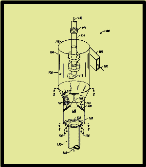
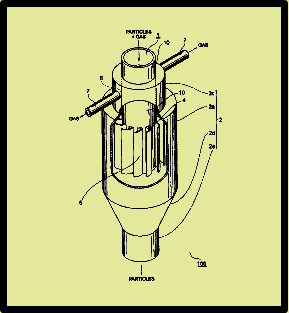
U.S. Patent No. 8,192,614, assigned to Kellogg Brown & Root LLC, generally relates to a self-stripping cyclone (see figure below) comprising a cyclone section and a stripping section, where the stripping section has a cross sectional area greater than the cross sectional area of the cyclone section. An inlet to the cyclone section allows tangential feed of a particulate-fluid suspension. A cylindrical surface within the cyclone section separates the particulates from the suspension and forms a vortex of reduced particulate content. A particulate discharge outlet to the stripping section is in the cyclone section, and a plurality of aperatures are disposed through a lower portion of the stripping section. A discharge line from the cyclone section is in communication with the vortex. The patent contains five independent claims (1, 5, 7, 9, and 12). Claim 1 is summarized in Table 3.
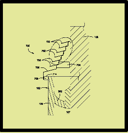
U.S. Patent No. 8,226,749, assigned to Kellogg Brown & Root LLC, generally relates to a rain shield for a cyclone (see figure below). The rain shield contains one or more cap portions disposed circumferentially around a cyclone outlet having ends further away and closer to the outlet. The rain shield also contains a series of support plates coupled to the cap portions and the outlet. A finish cap is circumferentially-disposed around the outlet of the pressure cyclone, and is coupled to the support plates and to a series of finish support plates, where the finish support plates are coupled to a vessel casing of the pressure cyclone. A plurality of rigid straps are coupled to the cap portions at the end further away from the outlet. Another plurality of rigid straps are coupled to the cap portions at the end closer to the outlet. A screen material coupled to the cap portions at the end closer to the outlet and is also coupled to the other plurality of rigid straps. The patent contains two independent claims (1 and 14). Claim 1 is summarized in Table 3.
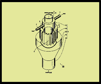
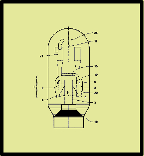
U.S. Patent No. 8,287,613, assigned to Shell Oil Company, generally relates to a gas-solids separator (see figure below). The separator comprises a tubular housing, an inlet for introducing a gas-solids mixture at one end of the housing, where the inlet imparts a swirl to the gas-solids mixture; a solids outlet at the opposite end of the housing; and a co-axially positioned tubular gas outlet conduit having a gas outlet conduit inlet end which extends through the end of the housing with the gas outlet conduit inlet end terminating within a separator zone defined by the tubular housing; a vortex stabilizer and a pin placed on a stabilizing plate and residing within the separator zone where the pin runs along an axis of the tubular housing and defines a passageway through the stabilizer plate and the pin. The patent contains two independent claims (1 and 9). Claim 1 is listed in Table 3.
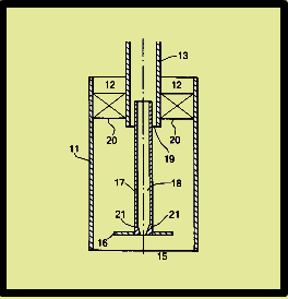
U.S. Patent No. 8,313,548, assigned to Japan Cooperation Center, Petroleum, and Nippon Oil Corporation, generally relates to a method of designing a gas-solid separator having an inner cylinder and an outer cylinder, the inner cylinder having a closed lower end and an opened upper end, and which extends in a vertical direction (note the gas-solid separator of U.S. Patent No. 8,083,824 described above) – see figure below. The outer cylinder coaxially covers the inner cylinder and has a gas vent port on the upper end side which communicates with an exterior. The inner cylinder has a plurality of axially extending long holes formed on a side surface on the lower end side of the inner cylinder in a circumferential direction. Each of the long holes has a guide blade that protrudes outward and is inclined circumferentially so as to cover the hole. The method comprises defining the number of the long holes, the opening area of the long holes, the outer diameter of the inner cylinder, the inner diameter of the inner cylinder, and the inner diameter of the outer cylinder to achieve a cross-sectional average linear velocity of a mixture of gas and solid particles that falls through the inner cylinder of 3 to 30 m/s, a cross-sectional average linear velocity of a mixture of gas and solid particles that is discharged from the long holes of 20 m/s or lower and a cross-sectional average linear velocity of a gas rising between the outer cylinder and the inner cylinder in a section where the long holes are formed of 6 m/s or lower. The patent contains a single independent claim which is summarized in Table 3.
U.S. Patent No. 8,361,202, assigned to IFP Energies Nouvelles, generally relates to a device for separating solid particles contained in a gas stream coming from the regeneration zone of a fluid catalytic cracking (FCC) (see figure below). The unit includes an inner envelope of cylindrical shape centered about the vertical axis of the regeneration zone, and an outer envelope that has one horizontal wall, one curvilinear wall, and one vertical wall, where the walls cover the inner envelope, and form a set of separation chambers radially distributed around the inner envelope in which the gas/solid suspension to be separated circulates, each separation chamber communicating, via inlet sections with the inner cylindrical envelope and, via outlet sections, with the lower part of the regeneration zone. The unit also has at least one side outlet located in the upper part of the side wall of the separation chamber, which is defined by the space between the portion of the vertical wall of the inner envelope located immediately below the inlet section and intrados corresponding to the curvilinear wall of the outer envelope. Baffles are located between two successive separation chambers, with each baffle being fixed to the wall of the inner cylindrical envelope. Return legs of the cyclones forming the secondary separation stage, are inserted between the separation chambers, and are aligned in a circle having a diameter between the diameter of the inner cylindrical envelope and the larger diameter of the outer envelope. The patent contains six independent claims (1, 7, 8, 9, 10, and 11). Claim 1 is listed in Table 3.
U.S. Patent No. 8,419,835, assigned to UOP LLC, generally relates to a cyclone comprising a barrel; a central hub positioned in the barrel to form an annular section between the central hub and the barrel, where the central hub has a lower, tapered section in the form of a conical end cap; and swirl vanes extending radially into the annular section over an axial length of at most 75% of an axial length of the central hub. The patent contains three independent claims (1, 9, and 17). Claim 1 is summarized in Table 3.
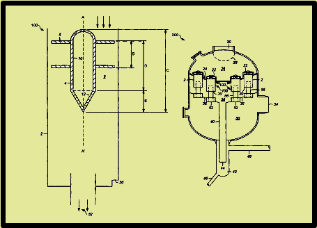
Table 1
FCC Patents—Cyclones
|
Patent Number |
Inventor |
Assignee |
Title |
Issue Date |
|
U.S. 8,083,824 |
Fujiyama et al. | Japan Cooperation Center, Petroleum, and Nippon Oil Corporation | Gas-Solid Separator |
Dec. 27, 2011 |
|
U.S. 8,192,614 |
Niccum et al. | Kellogg Brown & Root LLC | Self-Stripping FCC Riser Cyclone |
June 5, 2012 |
|
U.S. 8,226,749 |
Phillips | Kellogg Brown & Root LLC | System For Reducing Head Space In A Pressure Cyclone |
July 24, 2012 |
|
U.S. 8,287,613 |
Chen et al. | Shell Oil Company | Gas-Solids Separator |
October 16, 2012 |
|
U.S. 8,313,548 |
Fujiyama et al. | Japan Cooperation Center, Petroleum, and Nippon Oil Corporation | Method Of Designing Gas-Solid Separator |
Nov. 20, 2012 |
|
U.S. 8,361,202 |
Andreux et al. | IFP Energies Nouvelles | Gas/Solid Separation System For The Regenerators Of Fluid Catalytic Cracking Units |
Jan. 29, 2013 |
|
U.S. 8,419,835 |
Krishnamurthy et al. | UOP LLC | Apparatuses And Methods For Gas-Solid Separations Using Cyclones |
April 16, 2013 |
Table 2.
Cyclone Claims
| Patent Number |
Independent Claim |
|
U.S. 8,083,824 |
Claim 1. A gas-solid separator, comprising: an inner cylinder having a closed lower end and an opened upper end, and extending in a vertical direction; and an outer cylinder that coaxially covers the inner cylinder from the outside and has a gas vent port formed on the upper end side and communicating with an exterior, wherein a plurality of axially extending long holes are formed on a side surface on the lower end side of the inner cylinder in a circumferential direction, one of long side edge parts of each of the long holes is provided with a guide blade that protrudes outward and is inclined circumferentially so as to cover the long hole, and in a section of the outer cylinder that surrounds the plurality of long holes of the inner cylinder, an inner diameter D1 of a lower part of the outer cylinder is larger than an inner diameter D2 of an upper part of the outer cylinder, and an outer diameter D3 of a part forming the plurality of long holes in the inner cylinder is constant. |
|
U.S. 8,192,614 |
Claim 1. A particulate stripping unit with a self-stripping disengagement feature for separating particulates from a carrier fluid, comprising: a vessel having a cyclone section and a stripping section, the stripping section having a cross sectional area less than a cross-sectional area of the cyclone section; an inlet to tangentially feed a particulate-fluid suspension to the cyclone section; a cylindrical surface within the cyclone section to separate a major fraction of the particulates from the suspension and form a vortex of reduced particulate content; a particulate discharge outlet from the cyclone section to the stripping section; a plurality of apertures disposed through a lower portion of the stripping section; and a discharge line from the cyclone section in communication with the vortex. |
|
U.S. 8,226,749 |
Claim 1 A rain shield for a cyclone, comprising: at least a first sloped tray and a second sloped tray vertically disposed with respect to one another about a longitudinal axis, each tray having an aperture formed therethrough; at least one support member coupled to at least one of the first and second trays and extending toward the longitudinal axis; at least one support body coupled to at least one of the first and second trays and extending toward the longitudinal axis; a first plurality of straps coupled to an outer edge of the first and second trays; a second plurality of straps coupled to an inner edge of the first and second trays; and a screen at least partially disposed between the first and second trays; wherein an outlet of a cyclone is disposed through the apertures of the first and second trays such that the first and second trays are circumferentially-disposed about the outlet of the cyclone. |
|
U.S. 8,287,613 |
Claim 1. A gas-solids separator comprising: a tubular housing; an inlet for introducing a gas-solids mixture at one end of said housing, which inlet is executed such that it imparts a swirl to the gas-solids mixture; a solids outlet opening at the opposite end of said housing; and a co-axially positioned tubular gas outlet conduit having a gas outlet conduit inlet end and extending through an end of said housing with the gas outlet conduit inlet end terminating within a separator zone defined by the tubular housing; vortex stabiliser, comprising a pin placed on a stabilising plate, residing within the separator zone wherein the pin runs along an axis of the tubular housing and defines a passageway through the stabiliser plate and the pin. |
|
U.S. 8,313,548 |
Claim 1 A method of designing a gas-solid separator having an inner cylinder having a closed lower end and an opened upper end, and extending in a vertical direction; and an outer cylinder that coaxially covers the inner cylinder from the outside and has a gas vent port formed on the upper end side and communicating with an exterior; and a plurality of axially extending long holes formed on a side surface on the lower end side of the inner cylinder in a circumferential direction, one of long side edge parts of each of the long holes being provided with a guide blade that protrudes outward and is inclined circumferentially so as to cover the long hole, the method comprising defining the number of the long holes, the opening area of the long holes, the outer diameter of the inner cylinder, the inner diameter of the inner cylinder, and the inner diameter of the outer cylinder to achieve a cross-sectional average linear velocity of a mixture of gas and solid particles that falls through the inner cylinder of 3 to 30 m/s, a cross-sectional average linear velocity of a mixture of gas and solid particles that is discharged from the long holes of 20 m/s or lower and a cross-sectional average linear velocity of a gas rising between the outer cylinder and the inner cylinder in a section where the long holes are formed of 6 m/s or lower. |
|
U.S. 8,361,202 |
Claim 1 Device for separating solid particles contained in a gas stream coming from the regeneration zone of a fluid catalytic cracking (FCC) unit bounded by an inner envelope (3) of cylindrical shape centred about the vertical axis (11) of the regeneration zone (25), and an outer envelope (1) that has one approximately horizontal wall (15), one curvilinear wall (16), and one approximately vertical wall (17), the set of said walls (15, 16, 17) covering the inner envelope (3) and forming a set of separation chambers (2) radially distributed around the inner envelope (3) in which the gas/solid suspension to be separated circulates, each separation chamber (2) communicating, via inlet sections (4) with the inner cylindrical envelope (3) and, via outlet sections (5) with the lower part of the regeneration zone (25) and having at least one side outlet (6) located in the upper part of the side wall (22) of the separation chamber (2), said side outlet (6) being defined by the space between the portion of the vertical wall of the inner envelope (3) located immediately below the inlet section (4) and intrados (26) corresponding to the curvilinear wall (16) of the outer envelope (1), said device comprises, in addition, baffles (7) located between two successive separation chambers (2), each baffle (7) being fixed to the wall of the inner cylindrical envelope (3), and return legs (8) of cyclones (21) forming the secondary separation stage, are inserted between the separation chambers (2), and are aligned in a circle having a diameter between the diameter of the inner cylindrical envelope (3) and the larger diameter of the outer envelope (1). |
|
U.S. 8,419,835 |
Claim 1 A cyclone for a gas-solid separator, the cyclone comprising (a) a barrel; (b) a central hub disposed within the barrel to provide an annular section between the central hub and the barrel, wherein the central hub has a lower, tapered section in the form of a conical end cap; and (c) swirl vanes extending radially into in the annular section over an axial length of at most about 75% of an axial length of the central hub. |
[1] My thanks to Mr. Ken Peccatiello of Peccatiello Engineering (www.PeccatielloEngineering.com) for reviewing the text.
– Bill Reid
Check out Bill’s bio page
This article is for informational purposes, is not intended to constitute legal advice, and may be considered advertising under applicable state laws. The opinions expressed in this article are those of the author only and are not necessarily shared by Dilworth IP, its other attorneys, agents, or staff, or its clients.